Topic 11
Section outline
-
-
Temperature and Humidity with an AHT20 Sensor
Review:
Microcontrollers M _________and C_________
You have measured:
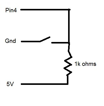
- switch condition (on/off)
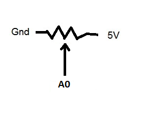
- voltage (potentiometer)
- distance
- time (with software)
- temperature
- humidity
You have controlled:
- LED (on/off)
- LED brightness (PWM)
- speaker (frequency, duration)
- LED strip (color and brightness)
types of resistor circuits:
Current Limiting, Pull Down, Voltage Divider (Potentiometer), Pull UpFun Fact:
Relative Humidity (%) is a measure of how close air is to being saturated with water vapor. Cold air can hold less water vapor than warm air so... as temp increases Rh(%) decreases - if water content stays the same as temp decreases Rh(%) increases - if water content stays the same 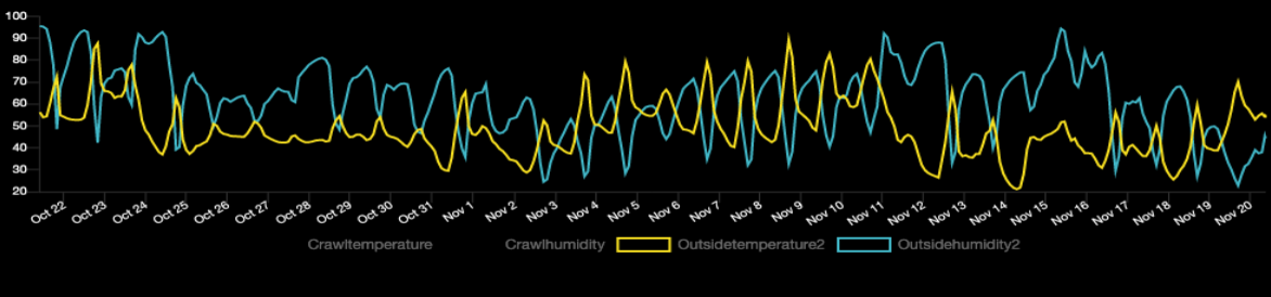
New Parts : AHT20 Temp & Humidity Sensor (4 Leads
LED Cup HolderDemo AHT20 - Link
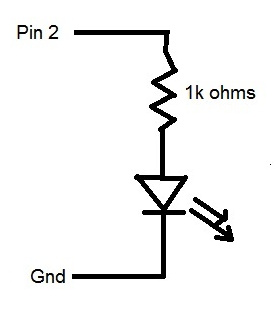
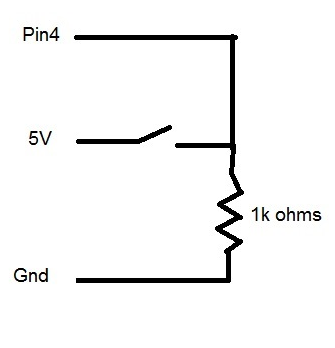
Breadboard Circuit:
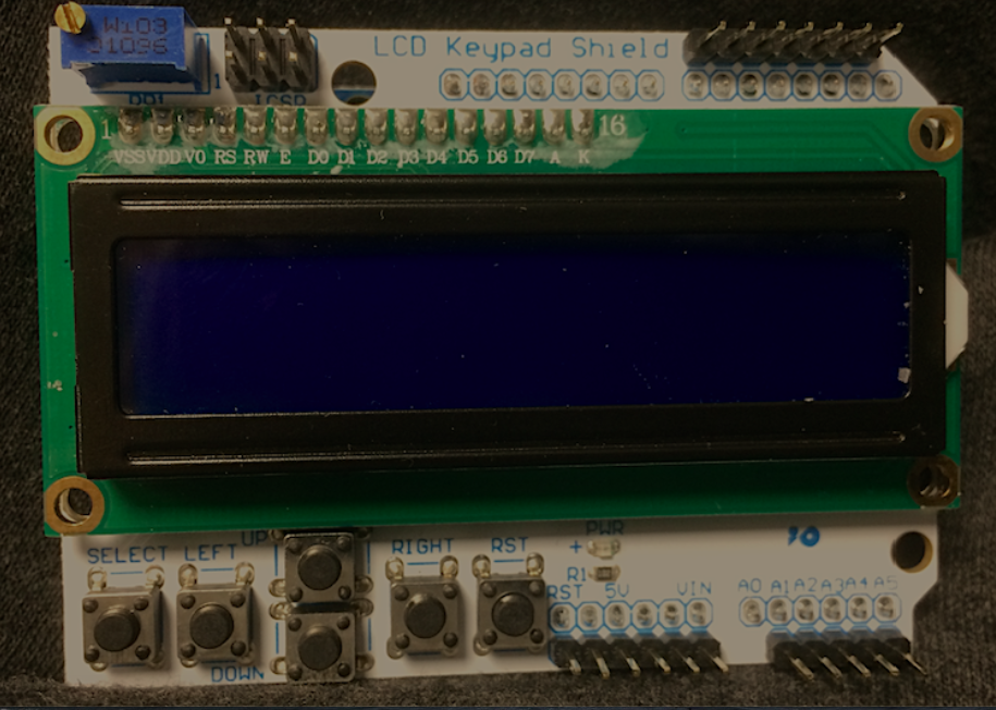
LCD Circuit:
AHT20 Pin --- Arduino Pin
Vin --- 5v
Gnd --- Gnd
SCL --- A5 (SCL)
SCA --- A4 (SCA)
Program to test the AHT20 writing data to the serial monitor:
Load this Analog Read Code to see how buttons on LCD are encoded to A0:
Click Here for Analog Read of A0
Load this program to exercise the LCD with Buttons:
Click Here for LCD Button Read
Assignment:
Create a sketch that:
Reads Temp and Humidity(%) and prints the Temp (F) and Humidity (%)
When the "Up" Button is pressed the Temp (C) is displayed for 2 seconds instead of Temp (F)
When the "Down" Button is pressed the Temp (K) is displayed for 2 seconds instead of Temp (F)
When the "Left" Button is pressed the LCD displays a NICE message to Mr. Suvar
Notes: F = 9/5 C + 32
K = C+273Temp variables should be floating point (not integer)
- switch condition (on/off)
-